A properly planned network cabling installation is the foundation of reliable connectivity in any commercial office. Without a comprehensive checklist, businesses end up with performance bottlenecks, costly rework, and infrastructure that cannot scale with future needs. This guide provides a step-by-step framework for planning, installing, and certifying a professional office network cabling system.
Pre-Installation Planning
The success of any network cabling project begins long before cable is pulled. A structured planning phase prevents installation mistakes that are expensive to correct later.
Site Survey and Needs Assessment
Walk your facility and document every location that requires network connectivity. This includes workstations, conference rooms, wireless access points, VoIP phones, printers, security cameras, and network equipment closets. Measure distances from each endpoint to the nearest intermediate distribution frame (IDF) or main distribution frame (MDF). If runs exceed 295 feet (90 meters), plan for intermediate switches or fiber uplinks.
Identify any obstacles such as HVAC ducts, electrical conduit, structural beams, or fire-rated walls that may affect cable routing. Document ceiling types, since drop ceiling installations are significantly faster and less expensive than hard-lid ceilings that require surface-mount conduit.
Capacity Planning for Growth
Design your cabling infrastructure for at least 50% more capacity than you currently need. A building that requires 80 network drops today should be designed with at least 120 drops to accommodate future expansion without major rework. This is especially important for fast-growing companies or multi-tenant office buildings where tenant configurations change frequently.
Consider future technology requirements. Many businesses now deploy multiple wireless access points per floor, video conferencing systems that require dedicated network runs, and IoT devices that were not part of the original design. Building excess capacity at the start avoids disruptive renovation later. For a deeper look at planning network capacity, refer to our guide on structured cabling fundamentals.
Budgeting and Timeline
Network cabling costs vary based on cable type, total linear footage, complexity of cable pathways, labor rates, and testing requirements. As a baseline, expect professional structured cabling services to cost between $150 and $350 per drop for standard office installations in accessible ceiling spaces. Costs increase for difficult installations requiring conduit, fire-rated walls, or plenum-rated cable in air-handling spaces.
Plan for at least two to four weeks from initial site survey to final certification for a typical 50- to 100-drop office installation. Large campus deployments or installations that require extensive conduit work may require several months.
Cable Type Selection Guide
Choosing the right cable category is one of the most consequential decisions in a cabling project. Each cable type has distinct performance characteristics, cost structures, and ideal use cases.
Cat5e vs Cat6 vs Cat6A vs Fiber
Cat5e (Category 5e): Supports gigabit Ethernet (1000BASE-T) at distances up to 328 feet. Cat5e is the minimum acceptable standard for modern office installations. While it is the least expensive option, it provides no headroom for higher-speed network upgrades and is rapidly becoming obsolete.
Cat6 (Category 6): Supports gigabit Ethernet and 10-gigabit Ethernet (10GBASE-T) up to 180 feet. Cat6 includes better shielding and crosstalk resistance than Cat5e, making it more suitable for environments with high electrical interference. This is the current industry standard for new commercial installations and provides a reasonable balance of cost and future-proofing.
Cat6A (Category 6A): Supports 10-gigabit Ethernet at the full 328-foot distance and is designed for high-performance networks. Cat6A cable is larger in diameter and more difficult to terminate, which increases both material and labor costs. It is the best choice for server rooms, data centers, and buildings where maximum performance and longevity are required. Most new enterprise-grade office buildings specify Cat6A as the baseline.
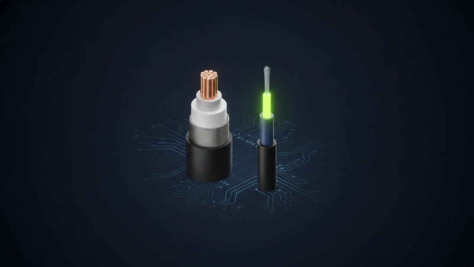
Fiber Optic: Supports speeds from 10 Gbps to 100+ Gbps over much longer distances than copper. Fiber is immune to electromagnetic interference and is ideal for backbone connections between buildings, IDF-to-MDF uplinks, and any run that exceeds 328 feet. Single-mode fiber is used for long-distance runs (multi-building campuses), while multi-mode fiber is typical for shorter inter-floor and intra-building runs. Learn more in our guide to fiber optic cabling services.
Plenum vs Riser Cable Ratings
Building codes require specific cable jacket ratings based on where the cable is installed. Plenum-rated cable (CMP) is required in air-handling spaces such as drop ceilings that serve as HVAC return plenums. Plenum cable uses fire-retardant materials that produce less smoke in case of fire, meeting strict fire safety codes. Riser-rated cable (CMR) is used in vertical shafts between floors but is not permitted in plenum spaces. Always confirm local building code requirements during the design phase to avoid costly cable replacement during inspection.
Infrastructure Requirements
Professional network cabling installations require more than just cable. The supporting infrastructure determines how well the system performs and how easy it is to manage and expand over time.
Cable Pathways and Support Systems
Structured cabling must be installed in an organized, code-compliant manner. Common pathway systems include:
- Cable trays: Metal ladder racks or solid-bottom trays mounted horizontally in ceilings or vertically in telecommunication rooms. Trays keep cables organized, prevent tangling, and make future additions easier.
- J-hooks: Suspended cable support rings mounted to ceilings, spaced every 4 to 5 feet to prevent cable sag and maintain proper bend radius. J-hooks are faster to install than trays and work well for smaller cable bundles.
- Conduit: Rigid metal or PVC conduit used when cables must run through walls, above hard ceilings, or in outdoor environments. Conduit adds significant labor cost but provides maximum protection and is often required by code in commercial buildings.
- Vertical riser pathways: Dedicated shafts or cable sleeves between floors for inter-floor connections. Riser pathways must use fire-rated sleeves and comply with fire stop requirements.
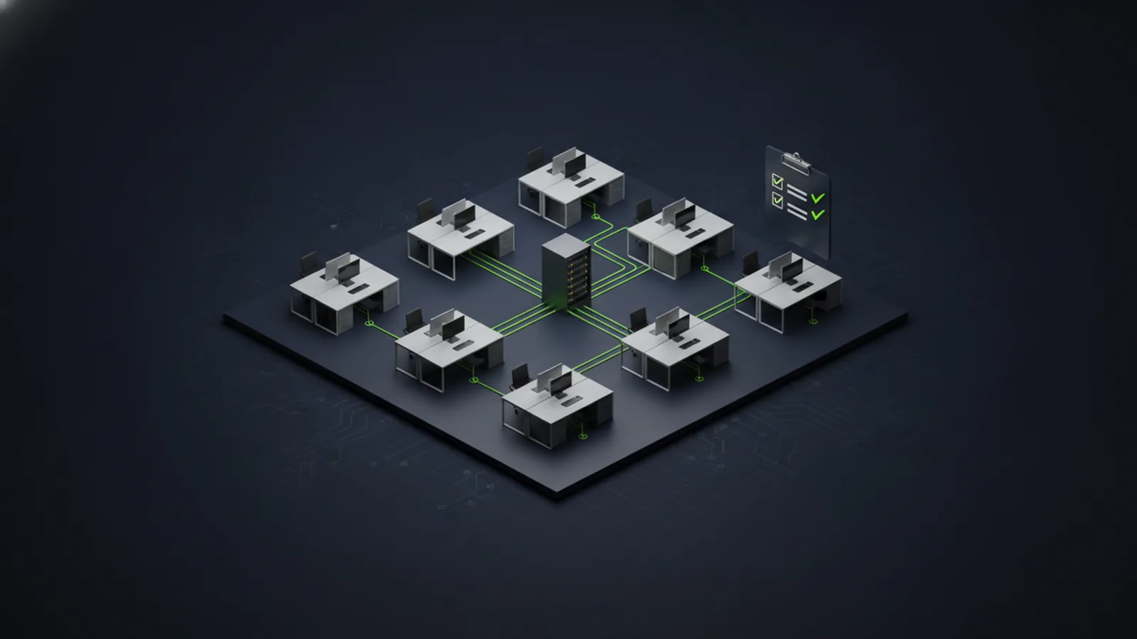
Patch Panels and Cable Management
Every cable terminates at a patch panel in the network closet. Use 24-port or 48-port patch panels mounted in standard 19-inch racks. Leave at least 1U of blank space between patch panels for cable management arms or horizontal managers. Label every port on both the patch panel and the wall jack with a consistent naming scheme that identifies location and port number (e.g., 2F-CONF-01 for second floor, conference room, port 1).
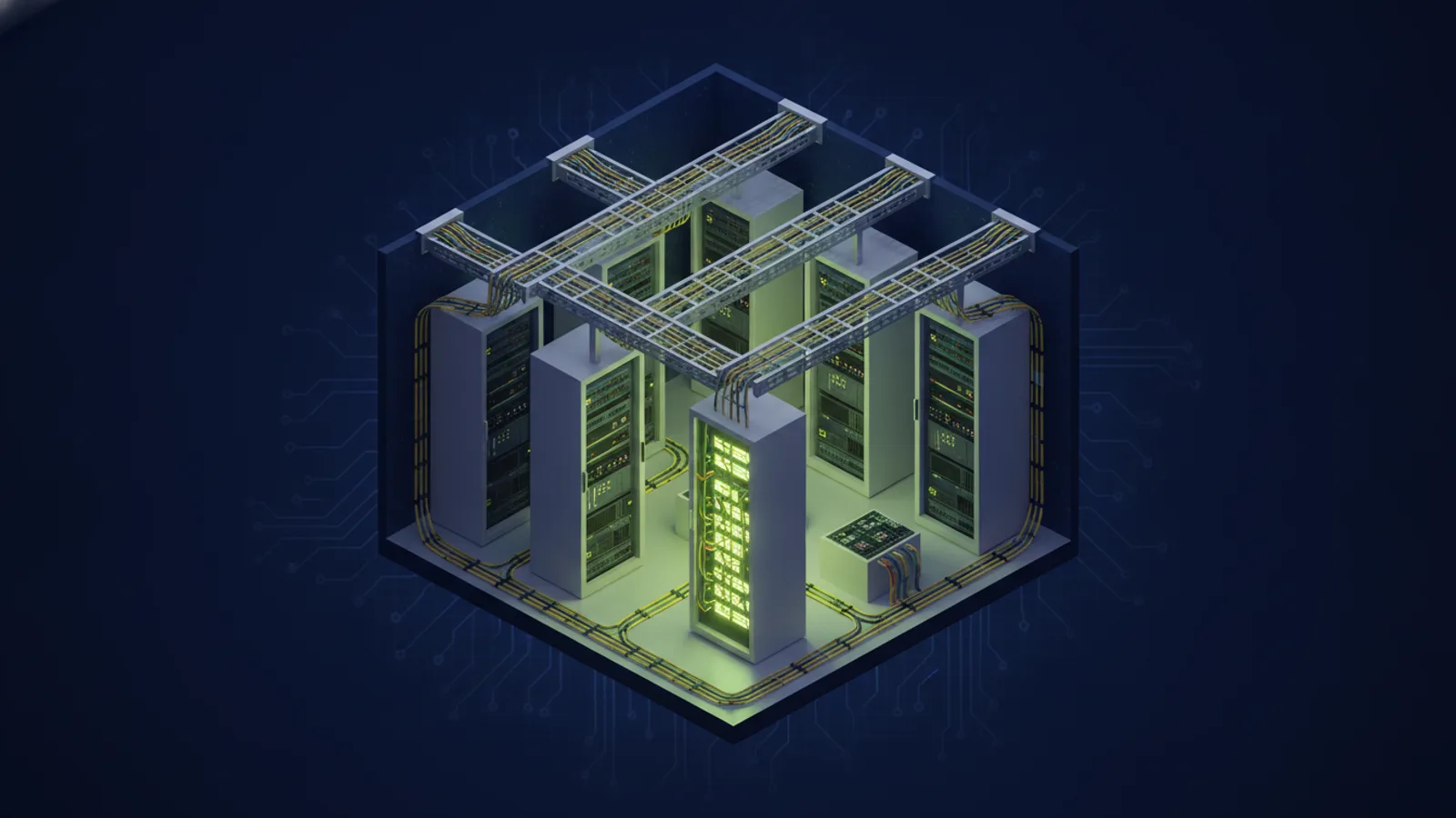
Network Closet / IDF Setup Checklist
Your network closet serves as the hub for all cabling terminations, network switches, and patch panels. A well-designed closet makes troubleshooting easier and ensures your equipment operates reliably.
- Minimum room size: At least 10 feet by 10 feet for offices with up to 100 drops. Larger buildings require multiple IDFs distributed across floors.
- HVAC: Dedicated cooling to maintain temperature between 64°F and 75°F. Network switches generate significant heat and will fail prematurely in unconditioned spaces.
- Power: Dedicated 20-amp circuits for network equipment. Include UPS (uninterruptible power supply) backup for switches and critical infrastructure.
- Rack installation: Use 42U four-post enclosed or open-frame racks. Mount switches, patch panels, cable managers, and power distribution units in an organized vertical layout.
- Fiber termination: Terminate fiber backbone cables in fiber distribution panels (FDPs). Protect fiber connections with dust caps when not in use.
- Labeling: Label every cable, switch port, patch panel port, and power connection. Use machine-printed labels for durability and legibility.
For more detail on managing complex network infrastructures, see our guide on managed network services.
Installation Best Practices
Professional cabling installations follow strict standards to ensure long-term performance and compliance with industry specifications. Cutting corners during installation leads to unreliable connections, failed certification tests, and expensive rework.
Pull Tension and Bend Radius
Never exceed the maximum rated pull tension for your cable type. For Cat6, the maximum pull tension is typically 25 pounds-force. Use cable lubricant in conduit runs to reduce friction. Install pull boxes in long conduit runs to allow staged pulls rather than one continuous pull that exceeds tension limits.
Maintain the minimum bend radius throughout the installation. For Cat6, the minimum bend radius is four times the cable diameter (approximately 1.5 inches). Bends that are too tight damage the internal wire pairs and cause performance degradation that may not appear until certification testing.
Separation from Electrical and Other Interference
Data cables must be separated from electrical power cables to prevent electromagnetic interference (EMI). Maintain at least 12 inches of separation from standard electrical lines and at least 24 inches from high-voltage lines or electrical panels. Where cables must cross electrical lines, cross at 90-degree angles to minimize interference exposure. For comparison of wired versus wireless network performance, see our post on wired vs wireless networks.
Termination Standards
Terminate all cables using either T568A or T568B wiring standards. Most commercial installations in the United States use T568B. Do not mix standards within the same installation. Maintain cable twist as close to the termination point as possible — untwisted pairs longer than 0.5 inches significantly degrade performance. Use professional-grade keystone jacks and punch-down tools, not cheap snap-in connectors.
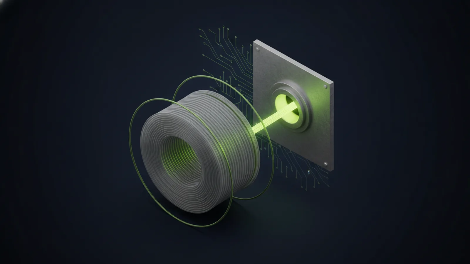
Testing and Certification
Every cable in a professional installation must be tested and certified to verify it meets the performance specifications for its category. Do not rely on visual inspection alone. Testing identifies installation defects before the system goes live.
Fluke Testing and Certification Reports
Use a dedicated cable certifier such as a Fluke DSX-5000 or DSX-8000 to test each cable. Certifiers verify that cables meet TIA/EIA performance standards for length, insertion loss, return loss, near-end crosstalk (NEXT), and other parameters. A passing test generates a detailed certification report that documents compliance. Many building owners and general contractors require certified test results before signing off on a cabling installation.
Do not use basic cable testers or tone generators in place of certification. These tools can verify connectivity but cannot measure performance characteristics required for compliance.
Documentation Package
Deliver a complete documentation package at project completion that includes:
- Certified test reports for every cable run
- As-built floor plans showing cable routing and drop locations
- Complete port labeling schedule linking wall jacks to patch panel ports
- Equipment rack layout diagrams
- Fiber splice documentation with loss budgets for each fiber run
- Warranty documentation and installer contact information
Store this documentation in both physical and digital formats. You will need it for troubleshooting, future expansion, and when selling or leasing the building.
Labeling and Documentation Standards
Effective labeling is critical for troubleshooting, adds and moves, and long-term system maintainability. Use a consistent naming scheme across the entire installation.
Wall jack labels: Identify building, floor, room, and port number (e.g., BLDG1-2F-205-A). Include the corresponding patch panel and port number for quick cross-reference.
Patch panel labels: Label each port with the same identifier as the remote wall jack. Use color-coded patch cables to distinguish different network zones (data, voice, access control, etc.).
Cable labels: Label both ends of every cable within 6 inches of the termination point. Use pre-printed wrap-around labels or adhesive flag labels that resist fading and tearing.
Digital documentation: Maintain a master spreadsheet or database linking every wall jack to its patch panel port, switch port, and VLAN assignment. This is essential for troubleshooting and network management in buildings with hundreds of network drops.
When to Hire a Professional Contractor
Network cabling installations for commercial offices require specialized tools, technical expertise, and strict adherence to industry standards. While small residential projects may be suitable for DIY installation, nearly all commercial deployments benefit from hiring a professional contractor.
DIY vs Professional Installation
DIY installation may be reasonable for very small offices with 10 or fewer drops, short cable runs in accessible ceilings, and no code compliance requirements. The tradeoff is no performance certification, no warranty, and limited recourse if the installation fails or does not meet performance expectations.
Professional installation is the right choice for any deployment involving more than a handful of drops, cable runs exceeding 100 feet, multi-floor buildings, installations requiring conduit or plenum cable, or projects where certified testing is required. A professional contractor provides engineering design, code-compliant installation, certified testing, comprehensive documentation, and warranty coverage.
Professional Ethernet installation costs more upfront, but the investment pays off in long-term reliability, performance, and resale value. Systems installed correctly the first time avoid the expensive rework and troubleshooting that plague low-quality installations.
What to Expect from a Professional Installer
A qualified structured cabling contractor should provide:
- Site survey and design: Detailed assessment of your facility, cable routing plan, equipment specifications, and project proposal.
- Certified technicians: Installers trained in TIA/EIA standards with current BICSI credentials or manufacturer certifications.
- Code-compliant installation: Full compliance with local building codes, fire codes, and ADA requirements.
- Professional-grade materials: Use of quality cable, jacks, patch panels, and cable management components from reputable manufacturers.
- Certified testing: Fluke or equivalent testing on every cable with detailed pass/fail reports.
- Documentation: Complete as-built drawings, port schedules, test reports, and warranty information.
- Warranty: Multi-year warranty on both materials and workmanship, typically 15 to 25 years for quality installations.
Unio Digital provides end-to-end network cabling services for commercial offices, medical facilities, educational institutions, and industrial sites throughout Arizona. From initial site survey through final certification, we deliver structured cabling systems designed for performance, reliability, and long-term value. For more guidance on designing comprehensive network infrastructure, refer to our complete guide to structured cabling services.
Need Office Network Cabling?
Get a free site survey and cabling design from our certified technicians.
Get a Quote